Waga produktu: 160g
Minimalna ilość w zamówieniu: 1
Ilość produktów w opakowaniu jednostkowym: 1
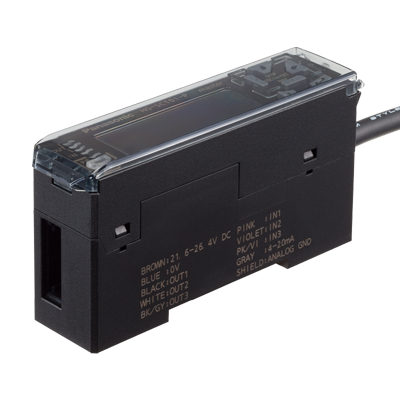
HG-T Laser thru-beam sensor, Controller, Master unit, PNP
| Item | Specifications | |||||||||||||
|---|---|---|---|---|---|---|---|---|---|---|---|---|---|---|
| Product Number | HG-TC101-P | |||||||||||||
| Part Number | HG-TC101-P | |||||||||||||
| Regulatory compliance | CE Marking (EMC Directive, RoHS Directive), UKCA Marking (EMC Regulations, RoHS Regulations) | |||||||||||||
| Pollution degree | 2 | |||||||||||||
| Operating altitude | 2,000 m 6561.68 ft or less (Note) : Do not use or store in an environment that has been pressurized to an air pressure higher than the atmospheric pressure at 0 m. |
|||||||||||||
| Environmental resistance : Protection | IP40(IEC) | |||||||||||||
| Environmental resistance : Ambient temperature | -10 to +50 ℃ +14 to +122 ℉ (No dew condensation or icing allowed) (Note), Storage: -20 to +60 ℃ -4 to +140 ℉ (Note) : When slave units are connected to the master unit, the maximum sink current / source current of control output and ambient temperature vary depending on the number of connected slave units as shown below.
|
|||||||||||||
| Environmental resistance : Ambient humidity | 35 to 85 % RH, Storage: 35 to 85 % RH | |||||||||||||
| Environmental resistance : Voltage withstandability | 1,000 V AC for one minute between all supply terminals connected together and enclosure | |||||||||||||
| Environmental resistance : Insulation resistance | 20 MΩ, or more, with 250 V DC megger between all supply terminals connected together and enclosure | |||||||||||||
| Environmental resistance : Vibration resistance | 10 to 150 Hz frequency, 0.75 mm 0.030 in double amplitude (10 to 58 Hz), Maximum acceleration 49 m/s2 (58 to 150 Hz) in X, Y and Z directions for two hours each | |||||||||||||
| Environmental resistance : Shock resistance | 98m/s2 acceleration (10 G approx.) in X, Y and Z directions five times each | |||||||||||||
| Material | Case: Polycarbonate, Cover: Polycarbonate, Switches: Polyacetal | |||||||||||||
| Cable | 0.2 mm2 2-core (brown and blue lead wires) / 0.15 mm2 7-core composite cable, 2 m 6.562 ft long | |||||||||||||
| Net weight | 140 g approx. | |||||||||||||
| Applicable sensor head | HG-T1010、HG-T1110 | |||||||||||||
| Maximum number of connectable controllers | Up to 15 slave units can be connected to a master unit. (Note) : When connected to a communication unit for digital displacement sensor, up to 14 slave units can be connected per master unit. |
|||||||||||||
| Supply voltage | 24 V DC ±10 %, including ripple 0.5 V (P-P) | |||||||||||||
| Current consumption | 100 mA or less (when sensor head is connected) (Note) : Current consumption does not include analog current output. |
|||||||||||||
| Analogue output : Analog voltage output | •Voltage output range: 1 to 5 V/F.S. (default value) •Linearity: ±0.05 % F.S. •Output when alarm occurs: 5.2 V •Output impedance: 100 Ω max. (Note) : Linearity is a value calculated from digitally measured values at F.S. = 16 mA for current output or F.S. = 4 V for voltage output. |
|||||||||||||
| Analogue output : Analog current output | •Current output range: 4 to 20 mA/F.S. (default value) •Linearity: ±0.25 % F.S. •Output when alarm occurs: 0 mA •Load impedance: 250 Ω max. (Note) : Linearity is a value calculated from digitally measured values at F.S. = 16 mA for current output or F.S. = 4 V for voltage output. |
|||||||||||||
| Control output(Output 1, Output 2, Output 3) | NPN open-collector transistor •Maximum sink current: 50 mA (Note) •Applied voltage: 30 V DC or less (between output and 0 V) •Residual voltage: 1.5 V or less (at 50 mA sink current) •Leakage current: 0.1 mA or less PNP open-collector transistor •Maximum source current: 50 mA (Note) •Applied voltage: 30 V DC or less (between output and +V) •Residual voltage: 1.5 V or less (at 50 mA source current) •Leakage current: 0.1 mA or less (Note) : When slave units are connected to the master unit, the maximum sink current / source current of control output and ambient temperature vary depending on the number of connected slave units as shown below.
|
|||||||||||||
| Control output(Output 1, Output 2, Output 3) : Short-circuit protection | Incorporated (automatic reset type) | |||||||||||||
| Control output(Output 1, Output 2, Output 3) : Judgment output | N.O. / N.C. switching type | |||||||||||||
| Control output(Output 1, Output 2, Output 3) : Alarm output | Open when alarm occurs | |||||||||||||
| External output switching | Output 1, Output 2, and Output 3 can be switched to 3-value, 2-value, Logic, and Logic 2. | |||||||||||||
| External input(Input 1, Input 2, Input 3) | Non-contact input or NPN open-collector transistor •Input conditions Invalid: +8 V to +V DC or open, Valid: 0 to +1.2 V DC •Input impedance: 10 kΩ approx. Non-contact input or PNP open-collector transistor •Input conditions Invalid: 0 to +0.6 V DC or open, Valid: +4 V to +V DC •Input impedance: 10 kΩ approx. |
|||||||||||||
| External input(Input 1, Input 2, Input 3) : Input time | • Trigger input: 2 ms or more (ON) • Laser emission stop input, preset input, reset input, bank input A/B(Note): 20 ms or more (ON) (Note) : Average count (response time) is for when the sampling cycle is set to 1 ms (standard sampling). Response times differ when the sampling cycle is set to 0.5 ms (high-speed sampling). |
|||||||||||||
| External input switching | Input 1, Input 2, and Input 3 can be switched to "Preset / Reset / Trigger", "Bank Input A / Bank Input B / Select (Preset, Reset, Trigger)", or "Laser emission stop". | |||||||||||||
| Sampling rate | 1 ms (standard sampling) / 0.5 ms (high-speed sampling) | |||||||||||||
| Average count (response time) | 1 time (2 ms), 2 times (3 ms), 4 times (5 ms), 8 times (9 ms), 16 times (17 ms), 32 times (33 ms), 64 times (65 ms), 128 times (129 ms), 256 times (257 ms), 512 times (513 ms), and 1,024 times (1,025 ms) switching type (Note) : Average count (response time) is for when the sampling cycle is set to 1 ms (standard sampling). Response times differ when the sampling cycle is set to 0.5 ms (high-speed sampling). |
|||||||||||||
| Display resolution | 1 μm 0.039 mil | |||||||||||||
| Display range | -199.999 to 199.999 mm -7.874 to 7.874 in | |||||||||||||
| Interference prevention function | Incorporated (Note) : This function operates for each set of 4 connected controllers. |
|||||||||||||
